|
 |
This install takes 4 to 7 hours (figure an all day job) and requires a lot of patience and may cause skinned knuckles and over abundant use of profanity. This is a DIY one should not take on lightly. One should be mechanically inclined, familiar with shift mechanisms and have the required tools in order to complete the job. This is not easy in any way shape or form and professional shops charge up to 4 hours of labor on a regular basis to install this kit. If all you've done is an oil change or brake pads, etc. think long and hard whether you want to really try this on your own. The only other thing to add is that its definitely worth it to install (or pay someone else to install) this kit since the results are terrific.
Click on the images for larger views. |
WARNING:
- NEVER get under a vehicle supported solely by a jack! If you use a jack to raise the car, make sure to use jack stands to support it.
- You will be working around the vehicle's exhaust. Once you have the car on ramps or jack stands let it sit and cool off before starting work.
|
NOTE: The some of the images below were taken with UUC or RE shifters in place. I have reused some parts of my UUC and RE SSK DIY's since they are the same as those required for the AS install. Also some of the images were taken on my 01 LSB (from UUC and RE installs) the AS specific images were taken on my 04 JB. The cars are identical so far as this DIY is concerned.
Also, thanks for Keith (KEF) for some of his images for this DIY. |
Step 1: Getting the required items together
This install requires:
- 1 AutoSolutions Ultimate Kit
- Jack and Jack Stands or Lift - Just ramps may work but will make your life far more difficult
- Hydraulic Jack
- A Set of Large Long Flat Screwdriver
- Small Flat Screwdriver
- Phillips Screwdriver
- Long Nose Pliers
- Snap Ring Pliers (if available)
- Socket Wrench & Extensions (3" & 8" or so)
- Torque Wrench (recommended)
- 8, 10, 13mm Sockets
- E14 Torx Socket
- 12, 13, 14mm Open Wrenches
- Synthetic Grease
- Wood Block (about 3/4" thick and about 3X3")
- Thick (about 3/4" dia) Wood Dowel or Brass Rod.
- Hammer / Mallet
- Flashlight / Shop Light
- Windex
- A BMW M3 (E46)
- 4 hours to a day of your life
|
 |
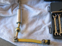
AS Shift Lever & Selector
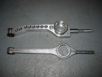
AS Carrier & OE Carrier |
Step 2: Remove shift boot
- Carefully pull up the driver's side forward corner of the shift boot (see image).
- Once you have the corner released, work the rest of the way around the boot to release it completely
- Pull the shift boot up over the knob.
|
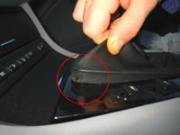
Removing the Shift Boot |
Step 3: Disconnect Power Lead and Remove Stock Knob
- Follow the wire that runs down from the stock knob to a connector.
- Disconnect the knob power wire from the car.
- Push the boot down to expose the knob.
- Using both hands, pull up on the knob to remove it - note: the knob is pretty tight, make sure not to smack yourself in the head with it once it releases from the shifter!
|
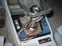
Location of the Power Wire |
Step 4: Removing the Center Trim and Insulation
- Remove the 2 screws at the back of the center panel.
- Disconnect the power window switch wiring (both sides).
- Remove the foam insulation piece (note its position)
|
Center Trim Bolt Locations
Window Switch Wiring
Shifter Insulation |
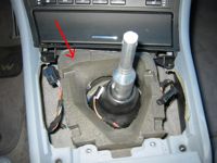
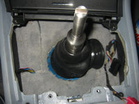
Step 5: Removing the rubber shift boot
- Pull up on the side of the rubber shift boot and pull it out of the opening in the body.
- Pull the rubber boot off the shifter.
|
Rubber Boot Released
Rubber Boot Removed |
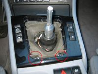
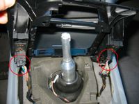
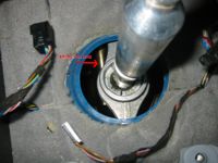
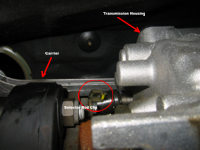
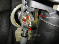
Step 6: Disconnecting the selector rod
- There is a retaining clip (just like the one that came with your kit) on the side of the shifter opposite to the selector rod. Visible from the passenger side.
- Some instructions say to do this step from under the car but I think its easier to do from inside the car.
- Using your long flat screwdriver, push the clip off the end of the selector rod (see image).
- Remove the plastic washer from the end of the selector rod (see image).
- Pull the selector rod out of the shifter (see image).
- Don't worry if the clip and washer fall under the car or on to the heat shield - you'll have plenty of opportunity to get at them in a bit.
|
Disconnecting Lever From Selector Rod
Close Up of Shifter Parts |
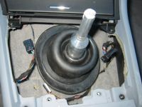
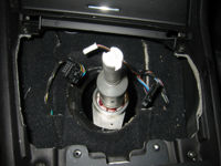
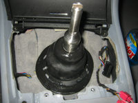
Step 7: Removing the stock shifter
- From inside the car.
- Follow the shifter down to locate the large white nylon cup that surrounds and the ball on the shifter.
- Use your long nose pliers to rotate the cup and release it from the vehicle (see image).
- Don't worry about damaging the nylon cup - you will not be reusing it (see image).
- Once the cup is released, lift the stock shifter up out of the car.
|
Nylon Cup Removal |
Step 8: Making room under the car
- From underneath the car, remove the large plastic panel located directly under the shift mechanism. The panel is attached via a number of 8mm bolts.
- Once you remove the plastic panel you will be able to see the a long exhaust heat shield located in the tunnel of underbody.
|
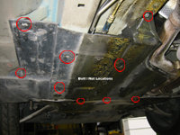
View From Under the Car
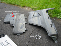
Shields Removed |
Step 9: Removing the mid pipe
- You have to remove part of the exhaust (mid pipe) to get enough room to get at the selector rod and carrier. First image shows the mid pipe removed.
- The front flanges of the mid pipe are attached via 2 screws each. One end is a torx E14 bolt and the other end is a 14mm nut. (see image)
- Hold the 14mm nut with a 14mm open wrench and use a socket wrench with the E14 torx socket to unscrew the bolts.
- The upper most of the two bolts on the outside pipe is a pain in the ass to get to - you will have to use a little body english to get your open wrench on the nut.
- Don't worry about the pipe landing on your head - there is a small extension from the headers into the mid pipe that will keep it in place.
|
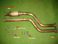
Mid Pipe and Hardware
Front Flanges
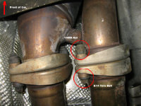
Flange Bolts Close-up |
Step 10: Removing the mid pipe part II
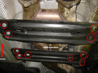
- Now remove the 6 bolts holding the back end of the mid pipe. (see image)
- The bolt is 13mm and the nut is 12mm - you a pair of open wrenches to take out all six bolts.
- Now worry about the pipe landing on your head!
- Also do not lose the 2 gaskets that are in-line at the connection between the mid pipe and the connecting pipe. If they are damaged you will have to replace them (pretty unlikely unless your car has a lot of miles on it).
|
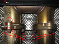
Rear Flange Close-up
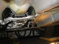
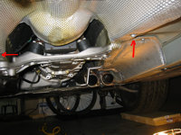
View with Pipe Removed |
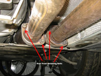
Step 11: Getting at the heat shield
- You have to at least loosen the heat shield to create enough room to install the selector rod and carrier.
- I did not completely remove the heat shield but loosened it up so that I could move it around as needed.
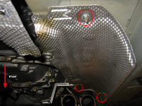
- Start by removing the 2 front bolts on the heat shield (10mm) (see image).
- Now remove the two large black brackets right at the front of the connecting pipe (13mm). The connecting pipe is also secured to the second bracket, don't worry it will not go anywhere when you take the bracket off (see image).
|
Two Front Bolts
Brackets |
Step 12: Removing yet another heat shield (last one!)
- There is a small heat shield on the passenger's side of the car going toward where the exhaust enters the engine bay. This one has to come out completely.
- Its secured by 3 10mm nuts (see image)
- Remove the nuts and pull the heat shield out of the car.
|
Bolt Locations |
Step 13: Removing the transmission brace
- There is a brace that goes across the tunnel toward the end of the transmission. This has to come off as well.
- Place a jack under the transmission to support it once the brace is removed.
- To remove the brace, first loosen the top bolts on the transmission mounts. This takes a 13mm open wrench. Loosen just enough for the nuts to turn freely by hand. (see image)
- Once the tops of the tranny mounts are loose, remove the 4 bolts securing the transmission brace to the underbody - don't worry the transmission is not going to fall out - you can then lower the jack supporting the transmission a bit to get more working room. (see image)
- Guess What! You're now ready to get back to working on the shifter!
|
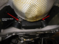
Tranny Mount Top Nuts
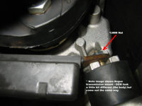
Tranny Mount Top Nut
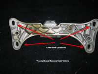
Tranny Brace Bolts |
Step 14: Removing the OEM selector rod
- There is a clip that locks the selector rod in place at the transmission. The clip is identical to the clip you removed from the other end of the selector rod (the one connected to the shift level).
- It is hard to see the clip but you should be able to get a glimpse of what you are doing from underneath the car.
- Use your long flat screwdriver to push the clip off the end of the selector rod pin.
- Remove the plastic washer off the end of the selector rod and pull the rod out of the car.
|
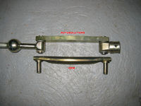
OEM and AS Selector Rods
View from Underneath |
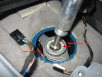
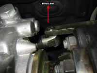
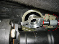
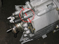
Step 15: On to the carrier
- There is a pin with a clip at the front end of the carrier that locks it in place. The clip has to have its tab released and rotated upward in order for the pin to be removed. (see images)
- Using your long flat screwdriver, pry under the edge of the clip and force it up. This is a royal pain in the ass as you will likely be unable to actually see the pin from under the car. You basically have to do this by feel. This may take a while, keep at it till the clip comes free and lets you rotate the pin.
- Once the clip is released, rotate it up and pull out the pin.
- Push the front end of the carrier up and out of its mounting location.
- The back end simply slides out of its mounting location so once you have the front end out its a snap to pull out.
- Pull the carrier completely out of the car and set it aside.
|
OEM and AS Carriers
Know Thy Enemy
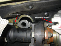
View from Underneath |
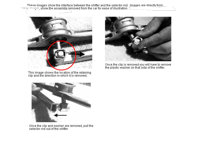
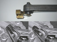
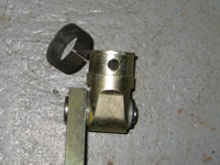
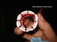
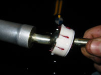
Step 16: Removing the Coupler - a.k.a. the real fun begins
- You now have to remove the coupler from the front of the transmission.
- This is the piece you disconnected the selector rod from earlier.
- To remove it you have to pop off the spring clip and pop out the retaining pin.
- If you look at the first image you can see how it all goes together - the second picture shows all of it apart.
- This is what worked for me: I rotated the spring in its groove so that the split in the spring was about a half an inch past the pin location (you can rotate the spring by hand).
- Then I forced a medium flat screw driver under the spring where it goes over the pin.
- Then using another screw driver (actually used a torx screw driver because of its flat round end) I pushed the clip off from where it splits. This took about half a dozen attempts and a bit of foul language.
- Once the spring is off you can use something like an Allen or Torx key to force the pin out of the couple (pretty easy).
- Once the pin is out the coupler will slide right off.
|
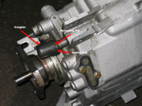
View From Top Of Tranny
This is a picture from another project - You will not disconnect the drive shaft or drop the tranny that far. It does show what you're after nicely though.
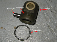
Coupler In Pieces |
Step 17: Disconnecting the Selector Rod from the AS Shift Lever
- For some ungodly reason the shift lever is shipped connected to the selector rod from AutoSolutions.
- Its not like at this point you're looking for more shit to take apart.
- Anyway, with a small screw driver carefully pop off the clip from the selector rod, remove the plastic washers and pull out the selector rod from the shift lever.
|
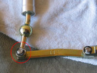
Clip on Selector Rod

Shift Lever and Selector Rod Separated |
Step 18: Installing the AS Coupler and Selector Rod
- You first have to pop the spring clip off the AS coupler.
- This is FAR easier than removing the clip off the OE coupler.
- A small flat screw driver will let you pop it right off - separate it at the split and work it off the coupler.
- The AS kit reuses the OE retaining pin.
- The coupler will slide right back into place the same way as the OE piece came off. Slide the spring clip on first and then the coupler.
- MAKE SURE YOU PUT THE SELECTOR ROD ON THE DRIVER'S SIDE! It will go in either way but you will not be able to shift into 3rd, 4th, 5th or 6th if you assemble it backwards.
- Run the pin through the coupler (you may have to push on the coupler to force it fully on).
- Pop the spring clip back into its groove and you're set with the selector rod for now.
|
Clip Off the AS Coupler
AS Coupler Installed |
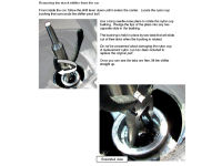
Step 19: Installing the New Carrier
- The bushing on the front of the AS carrier is VERY tight. This is further complicated by the fact that it has to be lined up perfectly with the "saddle" on top of the transmission housing and that all of this is done half blind.
- I found it impossible to push the carrier into the transmission housing by hand (others have had the same experience).
- An idea I did not try at the time might me to freeze the carrier so that the bushing shrinks a bit and makes it easier to fit.
- Some have even gone as far as putting chamfer on the bottom of the bushing in order to get it started into the transmission housing. I don't like this idea and did not do it.
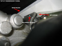
- Start by inserting the back of the carrier (pin end) into the rear carrier support (see first image). You may have to play with it a bit to go in and turn it right side up.
- I used a small wood block between the carrier (I greased the carrier and saddle) and the transmission tunnel and once the carrier was lined up I use my hydraulic jack to push the carrier into place. Be careful here not to over do it and by all means don't stick your hands in there while pressing.
- This will help you with pushing the carrier in but it will likely not get the carrier lined up well enough to slide the retaining pin back in.
- A mirror (one of the little dentist type - they sell them at auto parts stores) will be your best friend.
- Using the mirror you will be able to see how the brass bushing inside the nylon bushing in the AS carrier is lining up with the hole in the saddle on top of the transmission.
- If you need to move the carrier up you can use something like a 3/4" wood dowel and a hammer to tap it up. If it needs to go down you can use the same wood block and hydraulic jack method.
- Once its close you can use a set of picks or as I did a set of torx keys to work the carrier into final position.
- THIS IS A ROYAL PAIN IN THE ASS and will likely take some time to get perfect. The pin will not slide in unless everything is 99.9% aligned. Take your time and you'll get it but you'll hate every minute of it.
- If it makes you feel better its all down hill from here :-)
|
Rear of Carrier Installed
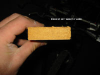
My Wood Block
Carrier "Saddle" On Transmission
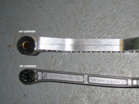
AS & OE Carriers
Note The Brass Bushing Inside
Carrier Being Pressed In
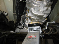
Carrier Being Pressed In |
Step 20: Installing the new shifter
- From inside the car.
- Use synthetic grease to coat the inside of the new nylon cup (see image).
- Insert the new shifter through the top of the nylon cup and snap in into place (see image).
|
All Greased Up and Ready to Go
Lever In Cup |
Step 21: Installing the new shifter part II
- Insert the shift lever with the nylon cup installed into the carrier cup and rotate the nylon cup to line up the tabs with the carrier's slots. You may want to us a small screwdriver to push the tabs into the carrier's slots.
- Pull on the shifter to make sure its locked in place.
- Note that the shift lever has a bend to it. Make sure that bend in the lever is pointed toward the back of the car. Rotate the lever as needed to achieve this (just the lever itself, not the nylon cup).
|
Shift Lever in Place |
Step 22: Connecting the selector rod to the shift lever.
- Back under the car we go.
- Replace the plastic washers (2) on the selector rod end.
- Push the selector rod through the shift lever (make sure the shift lever is facing the correct direction - bend toward the back of the car).
- Replace the plastic washers (2) on the selector rod and slide on the retaining clip.
- It helps to use something like a set of needle nose pliers to get the clip in place and make sure that it does not slide under the plastic washers while being pushed into place.
|
Selector Rod Connected |
Step 23: Reinstalling the transmission brace
- Note the slots on the transmission case that the tops of the transmission mounts slide into (see image).
- Work the bracket back into place - this take a bit of patience.
- Snug the nuts on the tops of the tranny mounts. Do not tighten them all the way down yet.
- Push the bracket as far toward the front of the car as it will go without undue force.
- Reinstall the bracket bolts and torque them to 21 ft lbs.
|
Transmission Mount Close Up |
Step 24: Tightening the tops
- Get your 13 mm box wrench out and reverse the steps you took to remove the upper nuts from the tranny mounts.
- Take your time and snug them down as much as you can - the factory torque for these is 15 ft. lbs. though I have no idea how you get a torque wrench in there.
|
|
Step 25: Replace the front heat shield
- Reverse the order in which you removed the front heat shield.
- Make sure you get the ends which over lap with other shields under those.
- Replace the 3 nuts on this heat shield and the one bolt on the heat shield you loosened.
|
|
Step 26: Replace the rear heat shield
- Reverse the order in which you removed the rear heat shield. See step 11.
|
|
Step 27: Replace the brackets
- Basically reverse the steps you took in Step 11.
- Replace the forward bracket first - torque the bolts to 21 ft lbs.
- The second bracket also acts as the support for the connecting pipe.
- Thread the two nuts that go to the connecting pipe mounts on first.
- Then attach the 4 bolts that go to the body and torque them.
- Then go back and tighten down the connecting pipe bracket bolts (see images in Step 11).
|
|
Step 28: Reinstall the mid-pipe
- Basically reverse the steps you took in Steps 9 &10.
- Examine the two exhaust gaskets - if they look to be in bad shape, replace them
- Start by sliding the mid pipe on to the front of the exhaust so that it has some support and does not fall on your head and then match up the rear flanges, insert the gaskets and tighten down the 6 bolts (bolt should be inserted from the back).
- Once the back of the pipe is tightened down, insert and tighten the 4 bolts there (torx end should point toward the rear)
|
|
Step 29: Finishing up under the car
- Replace the plastic covers/shields.
- You're done under the car! You can now lower the car off a lift or off jack stands. If you are using ramps, leave the car as it for now.
- Everything from here on out is done from inside the car.
|
|
Step 30: Reinstalling the rubber shift boot
- Spray the edges and the center section of the rubber boot with Windex (this will make it much, much easier to install).
- Locate the arrow on the edge of the rubber boot and line it up so that is faces forward.
- Slide the boot on to the shifter.
- Push the large under the lip of the opening in the floor - make sure you do not push the boot all the way through - there is a smaller lip on top of the large lip - this stays inside the vehicle.
- Work your way around the boot to make sure it is seated properly all the way around.
|
Rubber Shift Boot 'Windexed Up'
Rubber Shift Boot Partially In |
Step 31: Reassembling the center panel
- Reverse the steps you took in step 4.
- Make sure that the power lead for the knob is accessible and not trapped under the shifter insulation.
|
|
Step 32: Reinstalling the shift knob
- The factory knob simply snaps down into place.
- After the knob is snapped into place, reconnect the knob illumination power lead.
- Align the shift boot frame and snap it down into the center panel.
- Done! Go for a drive.
|
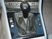
Completed Install |

|